GKE AI Series: First Training Job With JAX on TPUs
Training large machine learning models requires specialized hardware. Google’s Tensor Processing Units (TPUs) are among the best chips for this work. However, getting started with TPUs can be challenging—you need to understand chip layouts, configure node pools, and manage resources. It’s easy to get lost after browsing countless documents and troubleshooting errors for hours.
This series documents my learning journey and explains TPUs in plain language. I assume you’re familiar with basic GCP usage (the gcloud command) and Kubernetes concepts like Pods, Deployments, Nodes, and resource management. We’ll use the following terms throughout.
Terminologies
- TPU: Google’s specialized AI accelerator chip for machine learning. TPUs excel at matrix operations, making them faster than CPUs or GPUs for neural network training and inference. TPU v6e (Trillium) is the one of the available in GKE. TPUs are organized into “slices” connected via ICI (Inter-Chip Interconnect) for multi-chip training.
- GKE: Google Kubernetes Engine—Google Cloud’s managed Kubernetes service for deploying and scaling containerized applications. For TPU workloads, GKE offers TPU node pools, topology awareness, and integration with scheduling tools like Kueue. It’s recommended for its fault tolerance and simplified configuration.
- JAX: A Python library developed by Google for high-performance numerical computing and machine learning. It combines NumPy’s API with automatic differentiation and XLA compilation, making it ideal for TPU workloads. JAX automatically parallelizes computations across multiple devices, essential for multi-chip TPU configurations.
Understanding TPU Topology (Simplified)
The confusion: TPU topology sounds complex, but it’s simply about how chips are arranged. We’ll use TPU v6e (Trillium) as our example—it’s easier to understand with its 2D layout and offers excellent performance for training workloads.
Think of it this way:
- A chip = one processing unit (like a single brain)
- A topology = how chips are arranged in rows × columns (like seats in a theater)
- 2x2 = 2 rows × 2 columns = 4 chips total
Common TPU v6e configurations:
| Topology | TPU Chips | Hosts | VMs | Machine type (GKE API) | Scope |
|---|---|---|---|---|---|
| 1x1 | 1 | 1/8 | 1 | ct6e-standard-1t | Sub-host |
| 2x2 | 4 | 1/2 | 1 | ct6e-standard-4t | Sub-host |
| 2x4 | 8 | 1 | 1 | ct6e-standard-8t | Single-host |
| 2x4 | 8 | 1 | 2 | ct6e-standard-4t | Single-host |
Let’s start with the basics. A TPU chip is a specialized processor designed for machine learning workloads. When you hear “2x2 topology”, that simply means 4 chips arranged in a 2-row by 2-column grid. Physically, these chips may not form an actual 2x2 grid—they could be distributed across different locations within the host machine. What matters is the logical topology: how the TPU runtime organizes and addresses these 4 chips for distributed computation.
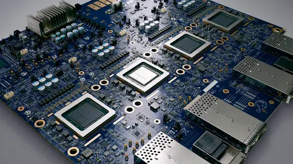
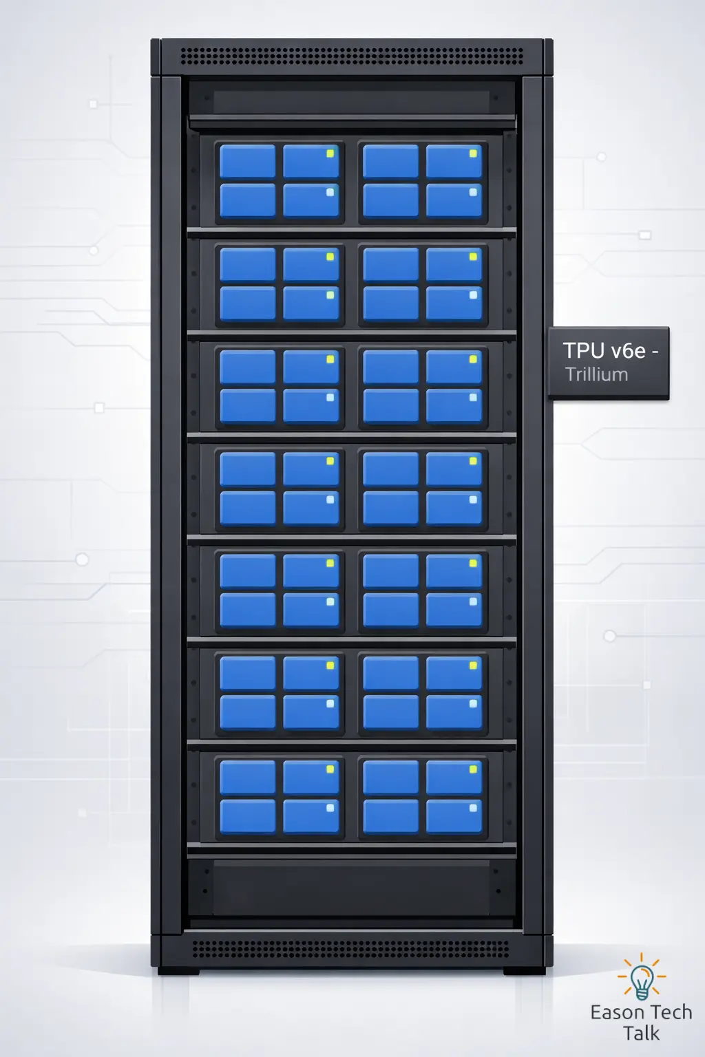
Below is a tray for TPU v6e (Trillium) deployed in Google datacenters. Each tray contains 4 chips and functions as an individual compute unit for machine learning jobs (source 1):
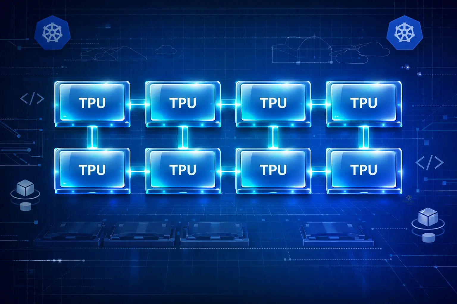
In reality, multiple trays can be connected in the datacenter to form larger slices for distributed training workloads. The diagram below shows chips and trays, where each blue block represents a chip. Four chips form one tray:
Knowing how these chips are separated can better help you understand topology form:
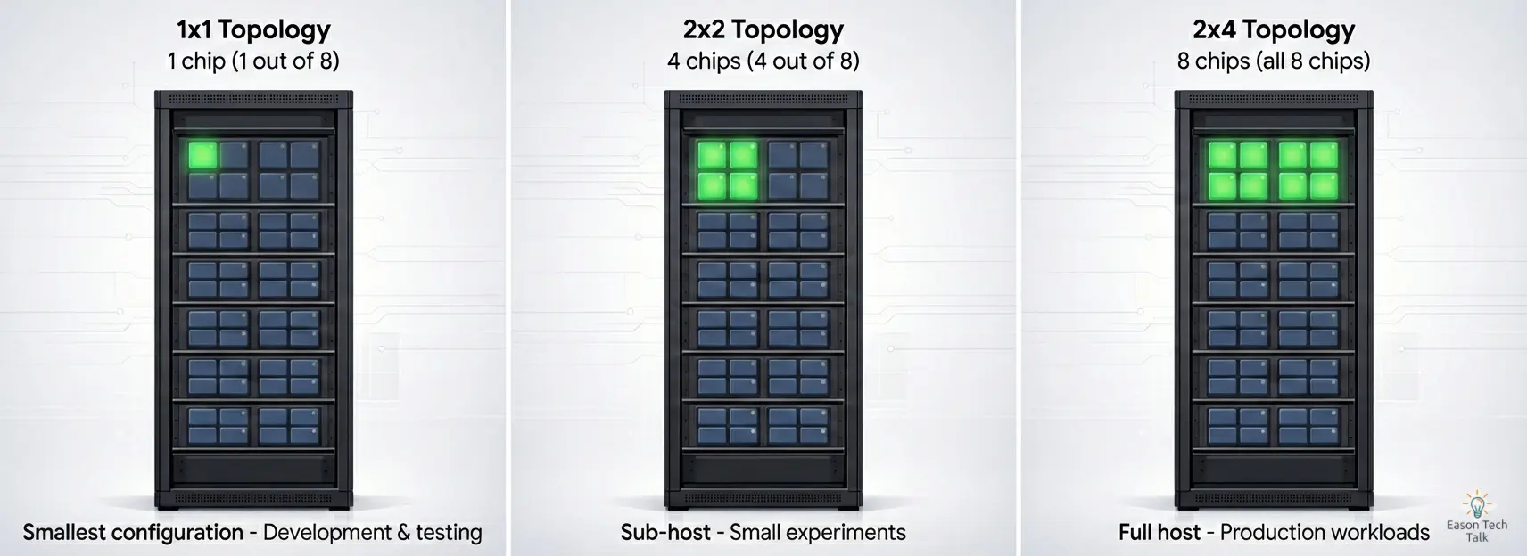
- In a 1x1 configuration, you’re using only 1 out of 8 chips on a single host. This is the smallest TPU configuration, ideal for development, testing, or running lightweight inference workloads.
- In a 2x2 configuration, you’re using only 4 out of 8 chips (highlighted in blue). This sub-host setup is perfect for smaller experiments or development work without renting the full machine.
- In a 2x4 configuration, you’re using all 8 chips on a single host machine (In a 2x4 configuration, you’re using all 8 chips on a single host machine (this may physically span two trays).
The following diagram showing how 8 TPU chips (represented as blue blocks) are arranged in different topologies.
How to use TPU in GKE
1. De-mystifying TPU (Uses v6e as example)
Before we touch any code, let’s understand how TPU rental actually works. Since this post focuses on using TPUs with GKE, I’ll start from the GKE perspective to explain TPU topology and how resources are allocated across nodes.
To understand how this works, I’ll use GKE Standard and its related machine types as examples.
The Machine: ct6e-standard-4t
In GKE, TPUs are attached to Virtual Machines (Nodes). The most accessible entry point for Trillium (v6e) is the ct6e-standard-4t machine type.
- 1 Node (VM) = 1, 4, or 8 TPU Chips. Each TPU v6e VM can contain 1, 4, or 8 chips. By default, a VM manages 4 chips unless you specify otherwise.
- The “All-or-Nothing” Rule: Unlike CPUs where you can request 0.5 cores, with TPUs on GKE, you generally must request all the chips on the node. You cannot request just 1 chip. If you rent the 4-chip machine, your Pod must request 4 chips.
GKE machine types that support TPU resources follow a naming convention: <version>-hightpu-<chip-count>t . The chip count indicates how many TPU chips are available to that VM. For example:
ct6e-standard-4tmeans 4 TPU chipsct6e-standard-8tmeans 8 TPU chipstpu7x-standard-4tsupports Ironwood (TPU7x) and contains four TPU chips
For a complete list of supported machine types in GKE, see Plan TPUs in GKE 2.
Understanding the Difference: Same Machine Type, Different Topologies
Let’s revisit the table:
| Topology | TPU chips | Hosts | VMs | Machine type (GKE API) | Scope |
|---|---|---|---|---|---|
| 2x2 | 4 | 1/2 | 1 | ct6e-standard-4t | Sub-host |
| 2x4 | 8 | 1 | 2 | ct6e-standard-4t | Single-host |
You might notice in the table above that ct6e-standard-4t appears twice with different topologies (2x2 and 2x4). This can be confusing for beginners, so let’s break it down.
The Key Insight: The machine type (ct6e-standard-4t) tells you how many chips your VM has access to, but the topology tells you how those chips are logically arranged for distributed computation.
Each VM sees its allocated chips (typically 4), allowing you to write programs that access and coordinate across all chips within that allocation.
Example 1: ct6e-standard-4t with 2x2 Topology
- What you get: 1 VM with access to 4 TPU chips
- Physical reality: These 4 chips are part of a single host machine (which has 8 chips total), but you’re only renting half of it
- Logical arrangement: The TPU runtime treats these as a 2×2 grid (2 rows, 2 columns)
- Use case: Smaller training jobs
Example 2: ct6e-standard-4t with 2x4 Topology (Multi-VMs)
- What you get: 2 VMs, each with access to 4 TPU chips (8 chips total)
- Physical reality: These 8 chips come from a single physical host machine, but they’re exposed as 2 separate VMs for orchestration purposes
- Logical arrangement: The TPU runtime treats these as a 2×4 grid (2 rows, 4 columns)
- Use case: Larger training jobs
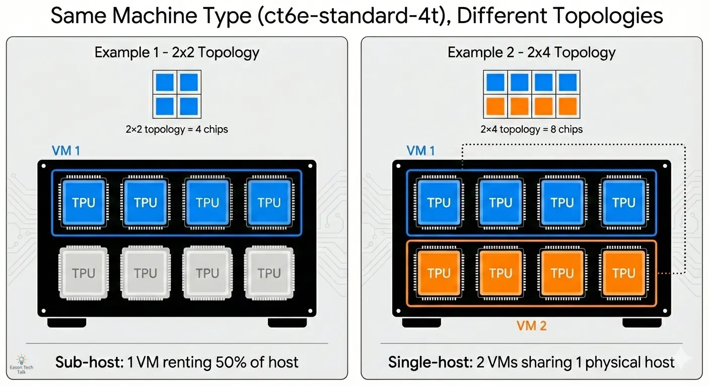
In a 2x2 configuration, your VM’s program can communicate with all 4 chips. In a 2x4 multi-VMs setup, each VM can access its own 4 chips, and the TPU runtime handles coordination between the two VMs to present them as a unified 8-chip system.
Why does this matter?
In GKE, each VM is a separate GKE node. For the 2x4 multi-host setup, you need to request resources across 2 nodes, not just 1.
This table shows how different topologies map to machine types and the number of GKE nodes your workload needs.
| Topology | Machine type | Total TPU chips | TPU hosts | Scope | TPU VMs | How many GKE nodes I needed? |
|---|---|---|---|---|---|---|
| 1x1 | ct6e-standard-1t | 1 | 1/4 | Sub-host | 1 | 1 |
| 2x2 | ct6e-standard-4t | 4 | 1/2 | Sub-host | 1 | 1 |
| 2x4 | ct6e-standard-4t | 8 | 1 | Single-host | 2 | 2 |
| 2x4 | ct6e-standard-8t | 8 | 1 | Single-host | 1 | 1 |
Understanding this mapping is essential when configuring your node pools, as you’ll need to ensure your cluster has enough nodes to accommodate your chosen topology.
2. Setting Up the GKE Cluster
Now that we’ve covered the fundamentals of TPU topology and machine types, let’s walk through the actual deployment process step by step.
We’ll use a 2x4 topology (8 chips) to run a small training job. First, we’ll create a standard GKE cluster and add a specialized node pool for our TPUs.
CLUSTER_NAME=tpu-quickstart         # Name of the GKE cluster
CONTROL_PLANE_LOCATION=us-central1  # Ensure you use region have v6e supported, see: https://docs.cloud.google.com/tpu/docs/regions-zones

gcloud container clusters create $CLUSTER_NAME --location=$CONTROL_PLANE_LOCATION
3. Create a node pool with flex-start
Next, we’ll add a node pool specifically configured for a 2x4 TPU workloads. This node pool will use the Flex-Start provisioning model to ensure we can secure TPU capacity even when demand is high.
NODE_POOL_NAME=nodepool   # Name of the GKE node pool
NODE_ZONES=us-central1-b  # Ensure you use zone have v6e supported, see: https://docs.cloud.google.com/tpu/docs/regions-zones

gcloud container node-pools create $NODE_POOL_NAME \
    --cluster=$CLUSTER_NAME \
    --location=$CONTROL_PLANE_LOCATION \
    --node-locations=$NODE_ZONES \
    --machine-type=ct6e-standard-4t \
    --tpu-topology=2x4 \
    --reservation-affinity=none \
    --enable-autoscaling \
    --num-nodes=0 --min-nodes=0 --max-nodes=2 \
    --flex-start
The --flex-start flag is crucial here. It tells GKE to use the Flex-Start provisioning model, which queues your node pool creation request and provisions resources when available, rather than failing immediately if capacity is unavailable.
Let’s break down the key parameters:
--tpu-topology=2x4: Specifies the logical arrangement of TPU chips (8 chips total in a 2×4 grid)--machine-type=ct6e-standard-4t: Each node will have access to 4 TPU chips--enable-autoscalingwith--num-nodes=0: Starts with zero nodes and scales up only when workloads are scheduled--max-nodes=2: For a 2×4 topology, you need 2 VMs (nodes), so set max-nodes accordingly
Note: --max-nodes=2 is required for a 2x4 topology to acquire 8 chips. If you use --max-nodes=1 with ct6e-standard-4t, it won’t meet the topology requirements and will only acquire 4 chips - this becomes a 2x2 topology instead.
The Provisioning Model: Flex-Start
As TPU is limited resource, deployment failure due to resource unavailable (when Google runs out of machines) are a common pain point. Flex-Start is a specialized mode that helps avoiding this.
| Feature | Standard On-Demand | Flex-Start |
|---|---|---|
| Cost | Standard Price | Discounted (typically ~40% off) |
| Availability | Immediate (if available) | Higher probability (you join a queue) |
4. Run a batch workload
Now that we have our GKE cluster and node pool configured, let’s deploy a simple training workload.
We’ll create a Job that schedules a TPU node with Flex-Start VMs. A Job controller in Kubernetes creates one or more Pods and ensures they successfully complete a specific task.
Here’s a simple YAML manifest that demonstrates how to deploy a training job on our TPU node pool:
apiVersion: v1
kind: Service
metadata:
  name: headless-svc
spec:
  clusterIP: None
  selector:
    job-name: tpu-training-job
---
apiVersion: batch/v1
kind: Job
metadata:
  name: tpu-training-job
spec:
  backoffLimit: 0
  completions: 2
  parallelism: 2
  completionMode: Indexed
  template:
    spec:
      subdomain: headless-svc
      restartPolicy: Never
      nodeSelector:
          cloud.google.com/gke-tpu-accelerator: tpu-v6e-slice
          cloud.google.com/gke-tpu-topology: 2x4
      containers:
      - name: tpu-job
        image: us-docker.pkg.dev/cloud-tpu-images/jax-ai-image/tpu:latest
        ports:
        - containerPort: 8471 # Default port using which TPU VMs communicate
        - containerPort: 8431 # Port to export TPU runtime metrics, if supported.
        securityContext:
          privileged: true
        command:
        - bash
        - -c
        - |
          python -c 'import jax; print("TPU cores:", jax.device_count())'
        resources:
          requests:
            google.com/tpu: 4
          limits:
            google.com/tpu: 4
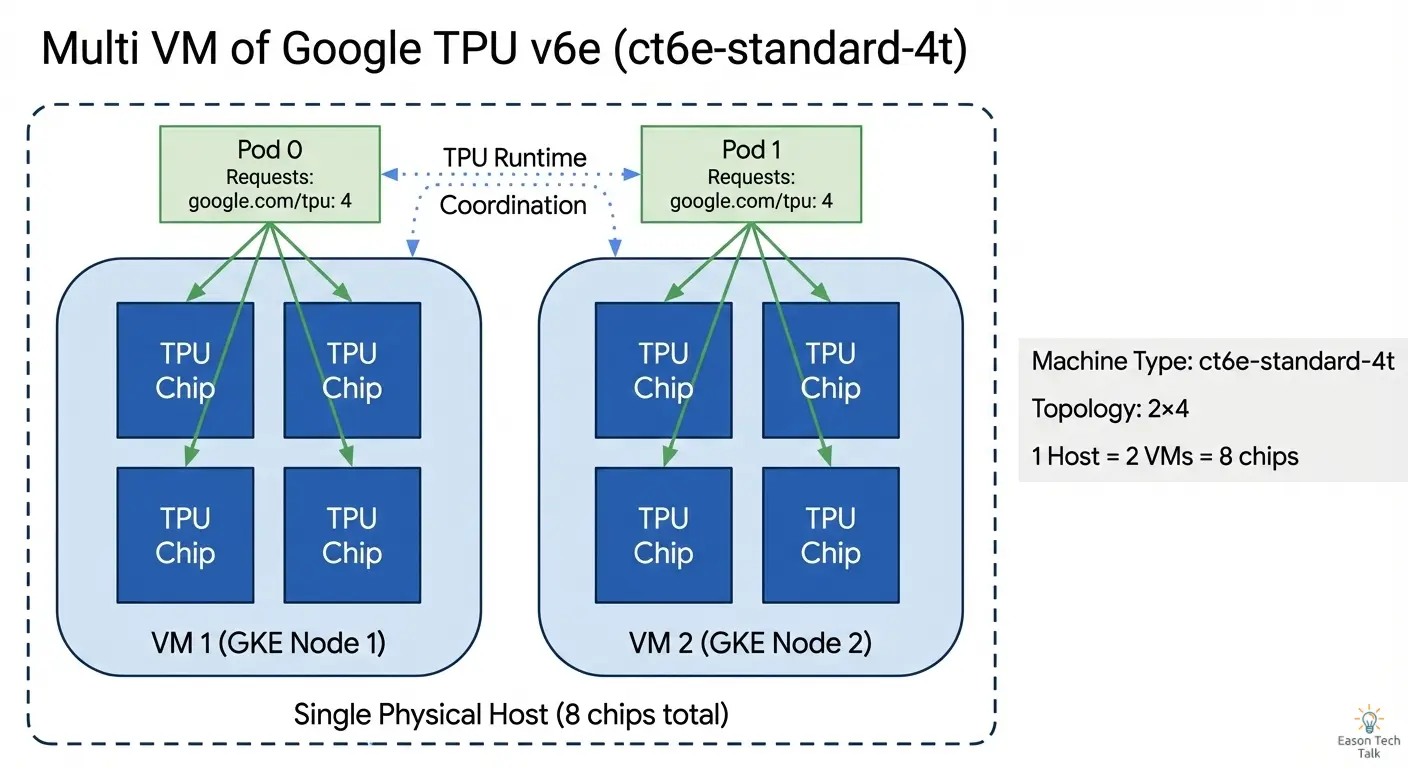
When you create a node pool with a 2x4 topology using ct6e-standard-4t, GKE provisions 2 separate nodes (VMs), each with 4 TPU chips.
The google.com/tpu: "4" resource request tells GKE to schedule the job on nodes with 4 TPU chips, matching our 2x4 topology. With parallelism: 2, two jobs run in parallel—one on each node. When you apply this manifest, GKE’s autoscaler automatically provisions the required nodes from your flex-start node pool if they aren’t already running.
Understanding the Kubernetes View: Node Scheduling
Let’s see how this looks from Kubernetes’ perspective. Run the following command to view your nodes:
kubectl get nodes -o wide
You’ll see output similar to this:
NAME                                      STATUS   ROLES    AGE   VERSION
gke-cluster-tpu-pool-a1b2c3d4-node-1      Ready    <none>   5m    v1.28.3-gke.1234
gke-cluster-tpu-pool-a1b2c3d4-node-2      Ready    <none>   5m    v1.28.3-gke.1234
To see the TPU-specific labels on these nodes, use:
kubectl get nodes -l cloud.google.com/gke-tpu-topology=2x4 -o json | jq '.items[].metadata.labels'
This will show labels like:
{
  "cloud.google.com/gke-tpu-accelerator": "tpu-v6e-slice",
  "cloud.google.com/gke-tpu-topology": "2x4",
  "google.com/tpu": "4",
  ...
}
Key observations:
- Accelerator label:
cloud.google.com/gke-tpu-accelerator: tpu-v6e-sliceidentifies the TPU hardware generation. This label is an enum configuration same as GKE Autopilot, documented in Plan TPUs on GKE 3 (Validate TPU availability in GKE > Autopilot). - Two separate nodes: For a 2x4 topology with
ct6e-standard-4t, you get 2 Kubernetes nodes - Each node has 4 chips: The
google.com/tpu: "4"label indicates the available TPU resources per node - Same topology label: Both nodes share the
cloud.google.com/gke-tpu-topology: 2x4label
Scheduling Your Workload Across Two Nodes
To utilize the full 2x4 topology (8 chips), your Job must schedule Pods on both nodes. This is why we set parallelism: 2 and completions: 2 in the Job manifest: one Pod per node.
Here’s how the scheduling works:
- Job creates 2 Pods: The Job controller creates 2 Pods with
completionMode: Indexed, assigning each a unique index (0 and 1) - Each Pod requests 4 chips:
google.com/tpu: "4"in the resource request - NodeSelector matches topology: The
cloud.google.com/gke-tpu-topology: 2x4nodeSelector ensures Pods land on the correct node pool - Scheduler distributes Pods: Kubernetes scheduler places one Pod on each node, satisfying the resource requirements
You can verify the Pod placement with:
kubectl get pods -o wide
You should see:
NAME                      READY   STATUS    NODE
tpu-training-job-0-abc    1/1     Running   gke-cluster-tpu-pool-a1b2c3d4-node-1
tpu-training-job-1-def    1/1     Running   gke-cluster-tpu-pool-a1b2c3d4-node-2
The -0 and -1 suffixes come from the Indexed completion mode, and each Pod runs on a different node, giving you access to all 8 chips in your 2x4 topology.
5. Review Training Job
After deploying the job, you can monitor its progress and verify that the TPU resources are being utilized correctly. Let’s check the job status and examine the logs to confirm everything is working as expected.
Check Job Status
First, verify that your job has been created and is running:
kubectl get jobs
You should see output like:
NAME                COMPLETIONS   DURATION   AGE
tpu-training-job    0/2           5s         5s
The COMPLETIONS field shows 0/2, meaning 0 out of 2 pods have completed. Once both pods finish successfully, it will show 2/2.
View Pod Logs
To see the output from your training job, check the logs of each pod:
kubectl logs tpu-training-job-0-<pod-suffix>
kubectl logs tpu-training-job-1-<pod-suffix>
You should see output confirming that JAX has detected the TPU cores:
TPU cores: 4
Each pod sees 4 TPU cores because each runs on a node with 4 chips. Together, they form the complete 2x4 topology with 8 total chips.
Troubleshooting Common Issues
If your pods remain in Pending state, check the events:
kubectl describe pod tpu-training-job-0-<pod-suffix>
Common issues include:
- Insufficient TPU resources: The flex-start node pool is still provisioning nodes. This can take several minutes.
- Node selector mismatch: Verify that your nodeSelector labels match the actual node labels in your node pool.
- Resource quota exceeded: Check your project’s TPU quota limits.
Bonus: Launch 8 Chips in a Single Host (Single VM)
For simpler deployments or when you want all TPU chips on a single VM, you can configure a 2x4 topology using a larger machine type that provides 8 chips in one node.
Instead of using ct6e-standard-4t which creates 2 separate VMs with 4 chips each, use ct6e-standard-8t to get all 8 chips on a single VM:
# Create TPU node pool for zonal cluster "my-cluster" in us-central2-b
gcloud container node-pools create tpu-pool \
    --cluster=my-cluster \
    --location=us-central2-b \
    --node-locations=us-central2-b \
    --machine-type=ct6e-standard-8t \
    --tpu-topology=2x4 \
    --reservation-affinity=none \
    --enable-autoscaling \
    --num-nodes=0 \
    --min-nodes=0 \
    --max-nodes=1 \
    --flex-start
Key differences:
- Machine type:
ct6e-standard-8tinstead ofct6e-standard-4t - Max nodes:
--max-nodes=1since you only need one VM - Single Kubernetes node: You’ll see only one node in
kubectl get nodes - All 8 chips accessible: Your workload can access all 8 chips from a single Pod
Update your Job manifest to run a single Pod instead of two:
apiVersion: batch/v1
kind: Job
metadata:
  name: tpu-training-job-single-host
spec:
  backoffLimit: 0
  completions: 1
  parallelism: 1
  template:
    spec:
      restartPolicy: Never
      nodeSelector:
          cloud.google.com/gke-tpu-accelerator: tpu-v6e-slice
          cloud.google.com/gke-tpu-topology: 2x4
      containers:
      - name: tpu-job
        image: us-docker.pkg.dev/cloud-tpu-images/jax-ai-image/tpu:latest
        securityContext:
          privileged: true
        command:
        - bash
        - -c
        - |
          python -c 'import jax; print("TPU cores:", jax.device_count())'
        resources:
          requests:
            google.com/tpu: 8
          limits:
            google.com/tpu: 8
This configuration is simpler because:
- You only need to manage one Pod instead of coordinating across multiple Pods
- No need for a headless Service for inter-Pod communication
- Easier debugging since all logs are in a single Pod
However, the multi-VM approach (ct6e-standard-4t) offers better flexibility for distributed training patterns when you need explicit control over workload distribution across VMs.
Conclusion
In this post, we walked through the complete process of running your first JAX training job on GKE with TPU v6e. We covered creating a GKE cluster, configuring a flex-start node pool with TPU topology, deploying a training job, and understanding how Kubernetes schedules workloads across TPU nodes. Whether you choose a multi-VM setup for distributed training flexibility or a single-VM configuration for simplicity, GKE provides the infrastructure to scale your ML workloads from experimental prototypes to production deployments.
References